Chaotic Oscillator Kit
The Chaotic Oscillator kit was designed by Professor Steve Gunn at the University of Southampton. If you have received one of these kits, the instructions below describe how to assemble your kit and realise its potential.
Circuit Schematics
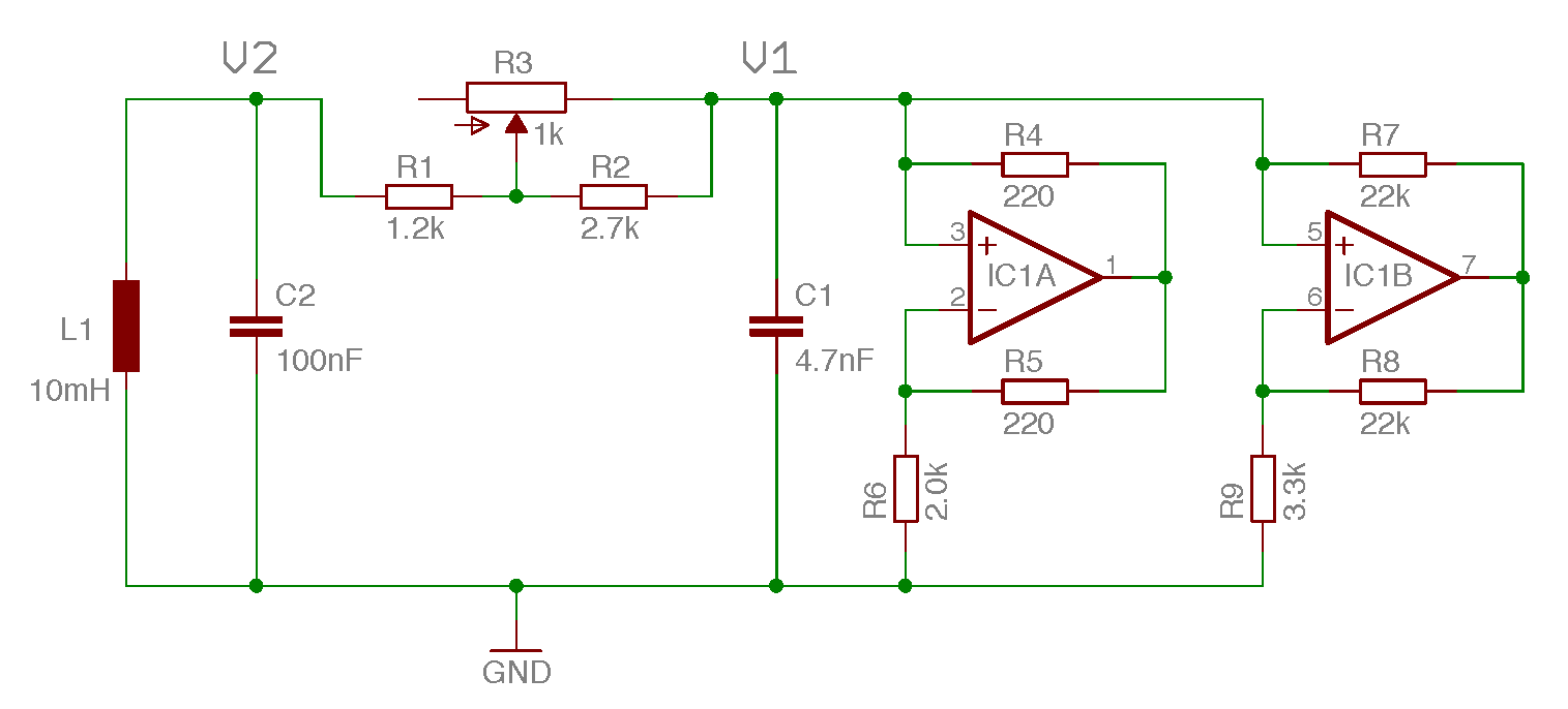
The Main Circuit
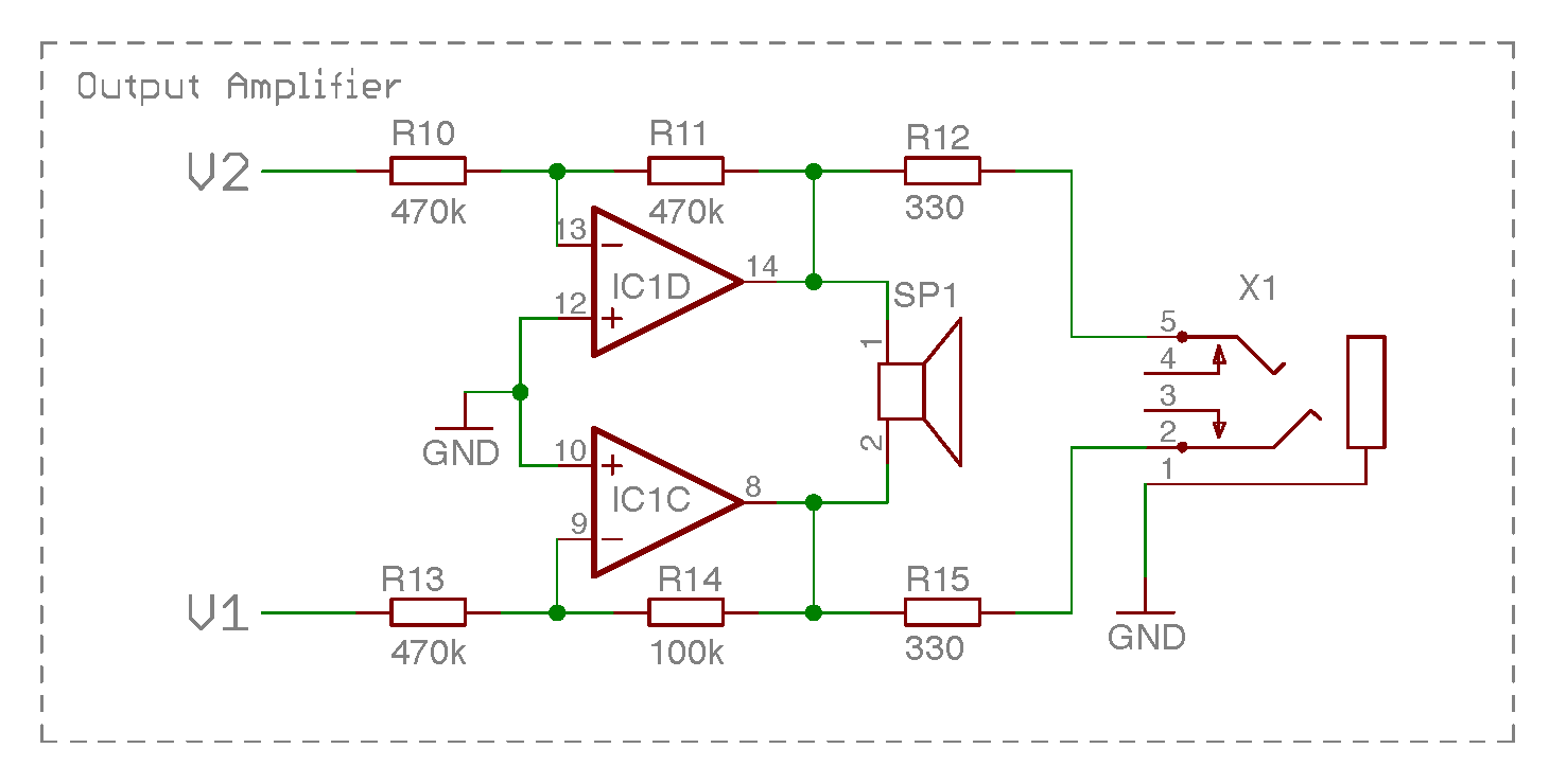
The Amplifier Circuit
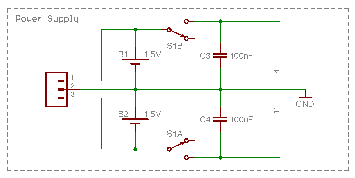
The Power Supply Circuit

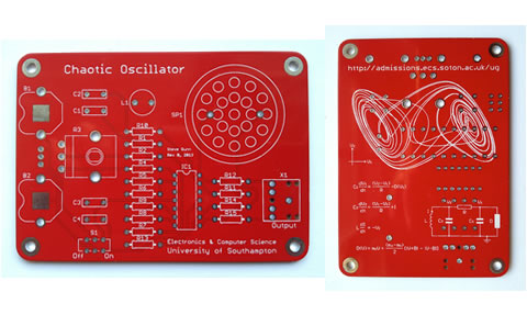
Kit Components
Construction
To build the circuit you will require some basic electronic tools. You can obtain a reasonable set of tools from any of the main Electronic suppliers. A couple of suitable kits would be the Rapid Electronics Tool Kit plus solder (£33), or if you are on a tight budget the CPC Soldering Kit (£10). Remember, in general you get what you pay for - more expensive tools from established companies will typically last longer and perform better.
If you haven’t done any soldering before, now is a perfect time to learn! This video provides a great tutorial on how to solder.
Resistors
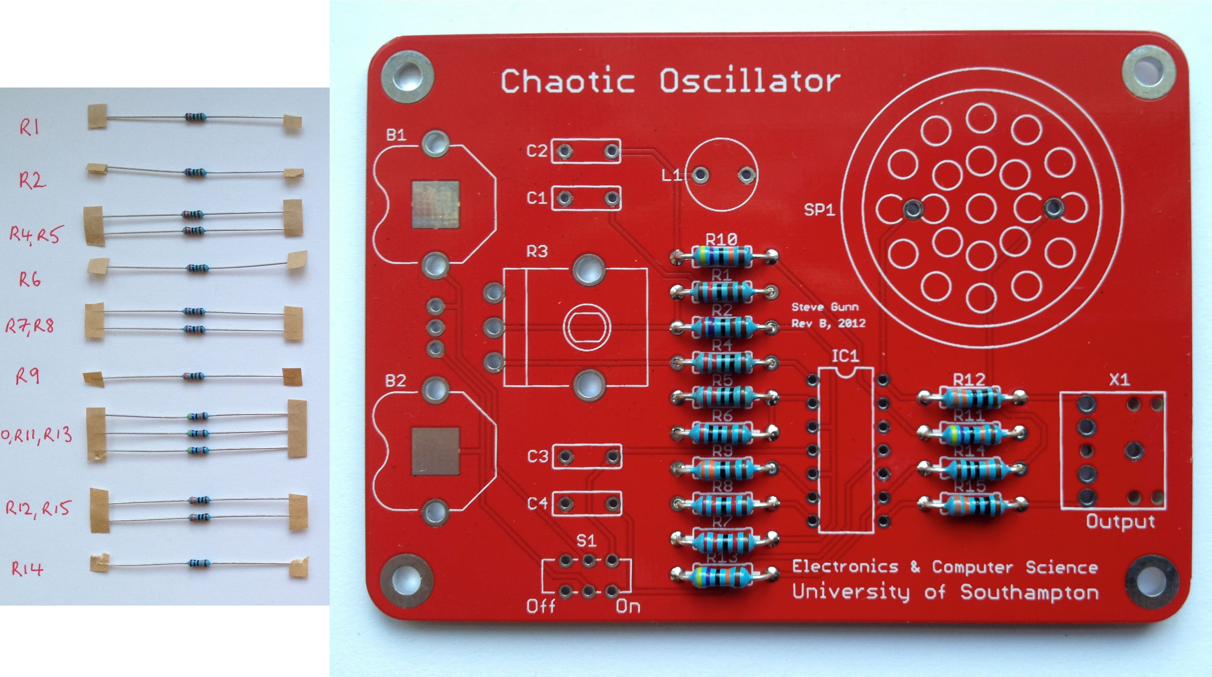
Start by fitting the fifteen resistors labelled R1-R15. Start by laying them all out on a piece of paper and labelling them according to their value. Their value is indicated by coloured bands (or could be checked with a multimeter).
Capacitors, Inductor and Potentiometer
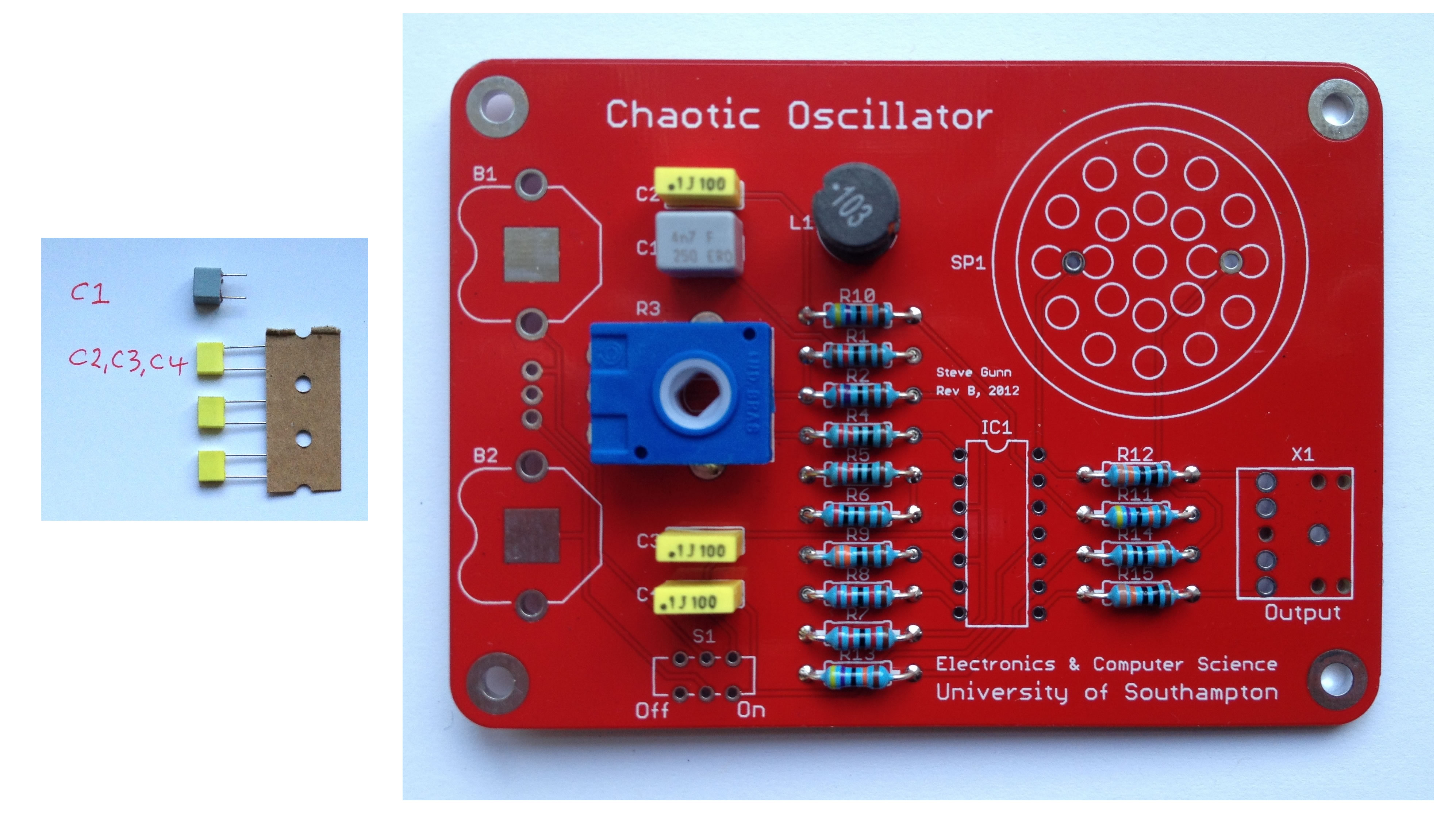
Next fit the capacitors, taking care to ensure that C1 is the 4.7nF capacitor. Then fit the inductor (L1). Finally fit the potentiometer (variable resistor) taking care to ensure that it is firmly pushed into the board before soldering.
IC socket, Battery holders, Switch, Speaker, Jack socket and IC
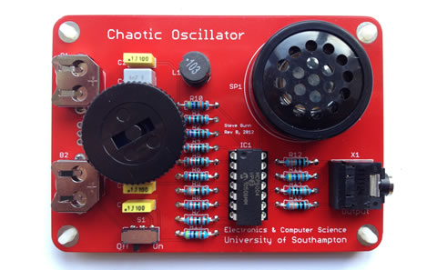
Next fit the IC socket, the battery holders (B1 and B2), the switch (S1). The speaker SP1 can now be fitted and it does not matter which way around it is fitted in this circuit. Finally fit the jack socket (X1). You have now finished the soldering aspect of the project. To finish up, fit the four plastic feet by pushing them into the holes from the underside of the board. Attach the potentiometer knob by inserting it from the top. Lastly, insert the IC taking care to ensure that the indent or dimple indicating pin 1 is in a NW orientation.
Audible Testing
Ensure S1 is in the off position and insert the two batteries with their positive terminals upper most. Turn on the switch S1 and rotate the potentiometer. If all goes well you should hear a range of noises as the potentiometer is varied which are centred around the main frequency of 4kHz. The sound is deliberately not too loud so as not to irritate. If you wish to hear it louder you can insert a pair of earphones into the 3.5mm jack socket or connect the system to a stereo amplifier.
Viewing the Chaotic Behaviour
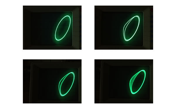
To see the real beauty of the chaotic behaviour you need an oscilloscope. Most of you probably have one, even if you did not realise it. It is possible to use the sound input on your computer as a low frequency oscilloscope which is sufficient for this exercise. Download the Soundcard Oscilloscope. This is a free program which converts the left and right channel from line in, to a two channel oscilloscope. Unfortunately, it is only available for Windows, so you will need to run it in a virtual machine if you are using a Mac or Linux. The oscilloscope is a tool to plot the dynamic behaviour of a circuit and enables us to see how voltages vary over time. Additionally, this oscilloscope enables us to display two inputs against each other in an X-Y mode revealing the nature of the chaotic attractor. Finally, it is even possible to look at the frequency content of the signals.

You will need a cable to connect your oscillator to your computer. The cable you require has a 3.5mm stereo jack plug on both ends and is sometimes shipped with iPods or music players. If you do not have one you can buy one from Rapid.
The circuit is quite sensitive to the precise component values and hence you may get some variation from the examples shown here.
As you increase the potentiometer you should be able to hear the oscillator go through a period doubling sequence before entering chaotic behaviour.
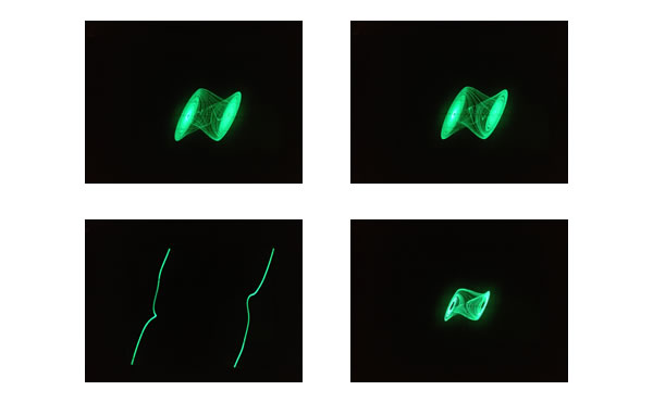
As you further increase the potentiometer you may be able to get the oscillator to show both sides of its attractor.
Further increasing the potentiometer will tend to shrink the attractor and in the limit will produce a stable (louder) oscillation around the main frequency of 4kHz.
Contact Us
For any enquiries, please email us at kits@soton.ac.uk.